
|
|
DDLBRAISDNBoardSettingsIn Brief The DDL card contains four RJ-45 type connectors for either subscriber line (S0, NT) or trunk line (T0, TE) connections. For proper S0 or T0 operation, correct hardware and software settings are necessary. RJ45 Pin Description Pin definitions of the RJ-45 connectors are as follows: 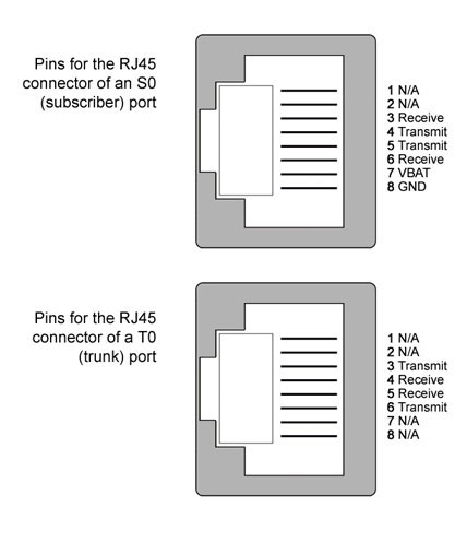 Jumper Settings Each port can be configured individually as a subscriber (S0, NT) or a trunk (T0, TE) through jumpers on it. Be aware that, setting jumpers only enables correct signals for S0 or T0 on RJ-45 connectors. For proper operation, software settings required by programming. By default, jumpers for all ports are set for S0 operation. 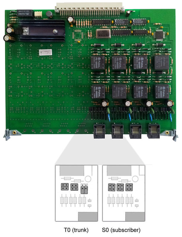 To set a BRI interface as a T0 (trunk), four conductor-pairs (of the relevant port) are short circuited with jumpers, whereas two others are left open as shown above. To set a BRI interface as an S0 (subscriber), all six conductor-pairs (of the relevant port) are short circuited with jumpers as shown above. ISDN Bus Connection Schemes Both point-to-point? and point-to-multipoint? connection schemes are possible. With point-to-multipoint connections, both short and extended passive buses are supported. Note that DDL ports have 100 ohms terminating resistors embedded on the board, so that there should not be near-end 100 termination in wiring. Software Setting By default, software settings for all DDL ports are S0. If you set jumpers of a DDL port for T0 operation, its software setting would not change automatically. It would be shown as S0 till you change its interface parameter. To do this, set 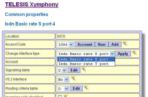 Important Notes
|