The Telesis PX24 mLrX system (AU) should be installed and serviced only by qualified personnel who has the necessary training about electrical equipment, and who understands the hazards that can arise when working on this type of equipment.
Finding Suitable Place for Installation
The installation site should be bright enough for ease of operation to the maintenance personnel. The site should have enough space. The system should be installed in a room where there is not too much occupancy. Finding a quite location for the operators telephone will reduce occupational strain on the working operator. Batteries that are connected to the system should be in a well ventilated area not too far away from the system. The 220 VAC mains connection should be grounded, the power should not be interrupted except for power outages. The ambient environmental conditions should be within the range of:
- Temperature range: 0-40
- Humidity range: %0-85 (non-condensing)
Ensure that the installation site does not contain:
- High voltage lines, smoke, dust, gas or radiation (such as a generator, photocopier etc.)
- Radio equipment that generates or emits high level signals
- Sever, pipes, or valves that could leak or cause condensation
- Vibration causing equipment
- Exposure heat sources or direct sunlight
Power
To ensure long operational life to your system and your safety, the 220 VAC outlet that connects to the system AC-DC power supply (i.e., adapter, converter) should provide phase-ground and phase-neutral voltage difference no more that 5V. Any auxiliary equipment that is connected to the system (such as a printer or a maintenance PC terminal) should use the same ground of the AC-DC power supply.
Input and output power specifications for the PX24 mLrX are:
- Input: 180 - 240 VAC
- Output:54 VDC (1.5 Amp)
Be aware
 | This system should be installed and serviced only by qualified personnel who has the necessary training about electrical equipment, and who understands the hazards that can arise when working on this type of equipment. |
 | The AC-DC power converter needs to be connected a grounded mains socket. |
 | External lines or outside lines that could be exposed to environmental conditions should be protected with secondary protective circuitry. |
| The MDF should be grounded. This ground should not be connected to the ground terminal of any other equipment (such as lightning ground, electrical transformer ground etc.) |
 | The battery to system connection should be made with a special cable supplied by Telesis. |
 | To minimize the risk of electrostatic damage to the system, serviceman should discharge of electrostatic buildup by wearing a shielded bracelet or take other necessary before handling electrostatic sensitive parts such as cards. |
 | This system is to be used in controlled environments where humidity and ambient temperature is maintained within working specifications and necessary precautions should be taken before leaving the equipment un-attendant. |
 | Disconnect all power sources from the system before servicing. |
| Do not remove or install cards to the system when it is powered up. |
| Attach all covers in place after servicing system and before leaving the customer premises to avoid customer contact with damageable components. |
| Any auxiliary equipment that is connected to the system should be set up according to its installation guide. |
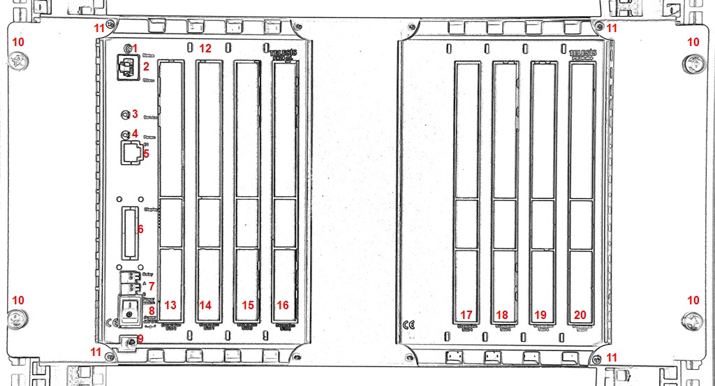
Front View of the PX24 mLrX
| 1 | Status led |
| 2 | Ethernet interface |
| 3 | Service button |
| 4 | Parameter button |
| 5 | E1 interface |
| 6 | LCD Panel |
| 7 | User controlled relay -A /B (Door opening etc.) |
| 8 | ON/OFF switch |
| 9 | PX24 mLrX power supply (power adapter) input |
| 10 | 19 inch rack mounting screws |
| 11 | Screws fixing the front panel to the system cabinet |
| 12 | Holes to hang front cover part onto the front panel |
| 13 | Expansion slot 1 |
| 14 | Expansion slot 2 |
| 15 | Expansion slot 3 |
| 16 | Expansion slot 4 |
| 17 | Expansion slot 5 |
| 18 | Expansion slot 6 |
| 19 | Expansion slot 7 |
| 20 | Expansion slot 8 |
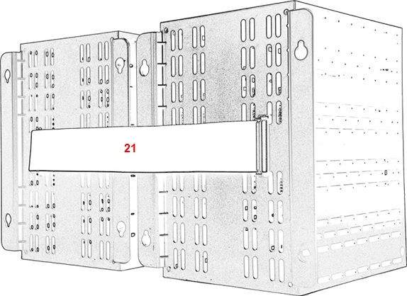
Back view of PX24 mLrX