Front view of the 19inch rack
Back view of the 19inch rack
If a single rack PX24xrX system is to be installed on the wall, wall mounting part 2.pxr7wllmnt shall be used.
The wall should be solid enough to carry the rack. The rack is hanged on the wall from the holes in its back.
- Make sure to keep cards in their electrostatically safe conductor bags when they are not installed in the system.
- Turn off the system and make sure the power supply LED is not lit. Failure to do so might damage your cards and your backplane resulting in system failure.
- Before handling cards, make sure you are electrostatically discharged by wearing an electrostatic bracelet or touching a metal object such as a radiator or a tap.
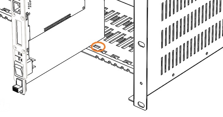
- On the back of the card there is a male connector with multiple pins. Make sure that none of these pins are bent or damaged.
- Hold the card with two hands, component side facing right, push it gently through the guides in the upper and lower part of the cabinet all the way until it clicks as the connector on the card mounts to the connector on the backplane. The cleats on the upper and lower side of the card should secure tightly into the holes in the rack.
- Never apply pressure, or force the cards into place, doing so may damage the connector pins causing a short circuit and resulting in system failure. If necessary, gently push the card to the left or to the right to align the connectors.
- To take out a card, push simultaneously on the cleats and pull with both hands, making sure you do not touch the components on the face of the card.
- Upload relevant license file to operate installed hardware.
- Visit System/License page to verify uploaded license file covers all installed hardware.

The power supply is installed in the leftmost part of the rack by pushing the power supply unit through the guides. Connect batteries with using 1.kblpxmuaku battery connection cables. If there are more than one power supplies or racks, connect power supplies to power terminals first with using 1.kblpxr7bat cables, then connect batteries to these power terminals.
Insert FAE (2.pxr7faexxx) control units into their dedicated slots. Be aware that there two such dedicated slots for 2.pxr7faexxx in a rack.
Important Notes
1. Each FAE unit supports maximum two DDS 2.ddskrtx001 digital subscriber boards. If there are more DDS boards in a system, distribute them accordingly among FAE controlled AUs.
2. Power supply connector and network switch connectors are different. Be careful to use correct cable while connecting power supplies and network switches.
To ensure long operational life to your system and your safety, all electrical components should be suitably grounded.
- A protective, independent ground terminal should be connected to the system
- The resistance of the ground and neutral terminals should not exceed 0.5 ohm
- The 220 VAC outlet that connects to the system power supply unit should provide phase-ground and phase-neutral voltage difference no more that 5V
- Any auxiliary equipment that is connected to the system (such as a printer or a maintenance PC terminal) should use the same ground of the system
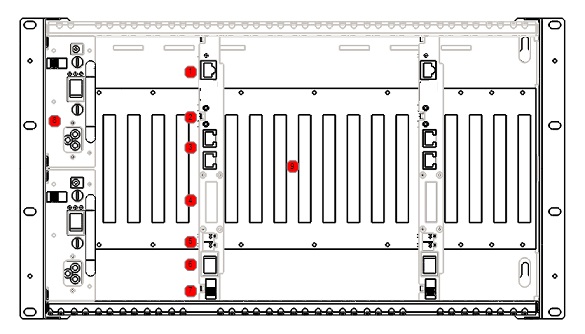
AUs are connected to 8 port switch as follows:
- AU1 is connected to the 1st port of the switch
- AU2 is connected to the 2nd port of the switchİki numaralı portu AU2'ye
- AU3 is connected to the 3rd port of the switch
- AU4 is connected to the 4th port of the switch
8th port of the switch is pre-programmed for mirroring. This port may used take records with using Wireshark for maintenance purposes. Do not connect any other equipment to the 8th port except for the purpose.
Front view after the installation
1 - Ethernet connector
2 - Service and parameter buttons
3 - E1 ports (optional)
4 - LCD
5 - Relay
6 - On/Off sswitch
7 - Locks for boards
8 - Power supplies
9 - Backplane and general purpose slots
The system operates from 220VAC, 50 Hz Mains. It is recommended to use additional batteries for power backup.